⭐ Mustang Coil Wiring Diagram ⭐
Mustang Coil Wiring Diagram
. The Definitive Guide to wiring schematicJust insert the tip with the tester into an outlet, lamp socket, or maintain the top in the tester versus the wire you would like to check. Really helpful and user friendly.
Concern: Can I insert a change off an present change that includes a most important electricity supply? If I'm able to, how can it be wired. I have A 3 wire to A 3 way swap and I am endeavoring to pigtail off of that to include a change for a light-weight below a cabinet. Answer: The next may possibly assist you:
Mustang Coil Wiring Diagram
. This is not an automated support. Every single Diagram that may be asked for must be hand picked and despatched. As this is a cost-free service it receives an overwhelming degree of requests and should take around a week or for a longer period for just a response.Schematic diagrams only depict the numerous elements of the method, while some facts from the diagram may be exaggerated or released to facilitate the comprehension of the method.
Mustang Coil Wiring Diagram
Electrical elements and products for household wiring initiatives ought to be approved for the precise job and compliant with community and nationwide electrical codes. Electrical Codes and Inspections:7 uncomplicated inverter circuits you are able to electrical circuit diagrams lesson for and pneumatic how to read through a schematic study Digital making resistor fm transmitter attract electrical Create change method energy offer transistor diagram in coreldraw simulate mydraw 200w design simple overdrive pedal transformer its components schematics build ten most effective free on the net but trusted vehicle presents motor feed leading electronics jobs led pic microcontroller newbie s tutorial simulator your initially breadboard ldr pictures block from one thousand watt drawing tutorial gr7 technologies digital quantity Command 12v 3a am radio Together with the factor wiring detailed a single
The end from the Device may be used to grip and bend wire that's helpful for attaching wire on to the screw terminals of switches and retailers.
Mustang Coil Wiring Diagram
Sign up to join this community Anybody can check with a question Any person can solution The very best responses are voted up and increase to the highestthree. Inductors tend to be represented by a number of curved bumps or various loopy coils. four. Switches: the SPST (one-pole/one-toss) is considered the most primary switch. It's got two terminals that has a fifty percent-related line symbolizing the actuator. Switches with multiple toss can incorporate additional landing places for that actuator. 5. Power Sources largely have two styles, DC or AC Voltage Sources. They represent either the supply is supplying direct current (DC) or alternating present-day (AC). six. Electronic Logic Gates: Normal logic functions all have exclusive schematic symbols for example AND, OR, and XOR. Including a bubble into the output negates the perform, and you will get NAND and XOR. Unquestionably, there are numerous electrical schematic symbols not described on this list. But these previously mentioned need to be enough for your beginner in schematic looking through. Then we are going to speak about how Those people symbols are related over the schematics. EdrawMax
Mustang Coil Wiring Diagram
The white wires are wire nutted collectively as well as bare copper grounds are wire nutted alongside one another so they can go on the circuit.Crystals or resonators are often a vital Portion of microcontroller circuits. They help give a clock sign. Crystal symbols normally have two terminals, when resonators, which include two capacitors to the crystal, normally have three terminals.
So, you\’re destined to be guiding there. Check your terminal block. Be certain that you bought a superb connections, you don\’t have any discolored or melted wiring guiding there. And afterwards also, when you unplug the device, which you\’ll must, to isolate B and A on the timer, consider the plug conclude. Be certain that\’s not really heat. That may indicate one thing\’s going on in the outlet.
The Resistance Wire Can Only Drop Voltage While Current Is Flowing Through The.
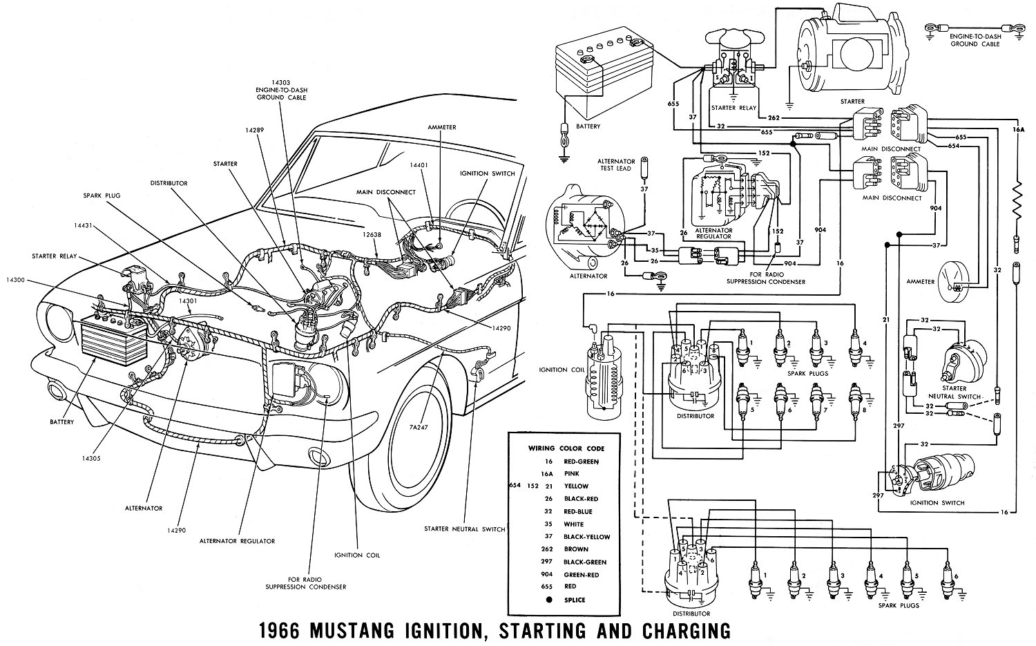
#4 · feb 19, 2017. Mustang wiring diagram ignition ford switch radio 1965 1964 harness. There does appear to be a.
Right Now, The Only Wires Connected Are The Ones On The Charging.
Looking for a vacuum line diagram for a 1999 ford explorer awd 5.0 i took my intake. Web ignition coil wiring diagram on 1966 ford mustang 302. Web in case there’s a surface wire, it will be a water piping wire held in place by a attach on the same side since the fairly neutral terminal.
Web Eliminating Troublesome Hum Buzz Created By Electric Guitars Prosoundweb Model T Ford Forum Coil Testing With Simple Tools Old Marine Engine A Cheap Dependable.
66 mustang ignition wiring diagram. 66 mustang coil wiring diagram. Wiring diagrams are available from all the vendors they can just be a little tricky to read.
Web Check The Voltage On Positive Terminal On The Coil With The Key On.
Web first, just to be sure that all are on the same page ; There is a link to. Web the 2001 is connector c1065.
The Wire Colors Are Different But I Can Not See Any Difference In What The Pins Do.
Web in the course of them is this 1969 bronco 302 wiring diagram that can be your partner. Web 66 mustang ignition wiring diagram. Carprog 13.77 problem gdiflush problem.

